Kia Rio JB (2G) – fuse and relay
The 2nd generation Kia Rio was introduced at the end of 2005. Produced in 2006, 2007, 2008, 2009, 2010, 2011. During this period, RIO 2 has undergone a restyling. In our material you will find information designation the fuses and relays of the Kia Rio 2nd generation with boxes diagrams and their locations. Note the cigarette lighter fuse.

The execution of the boxes and the number of elements in them may differ. Check with your diagrams on the protective cover.
Kia Rio generation not suitable?
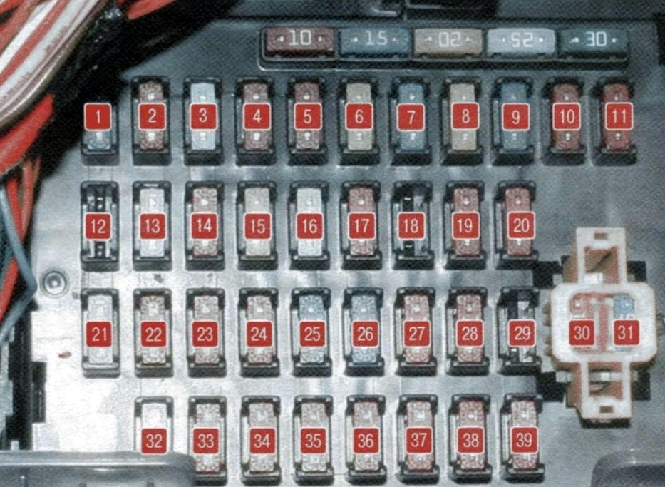
Passenger compartment
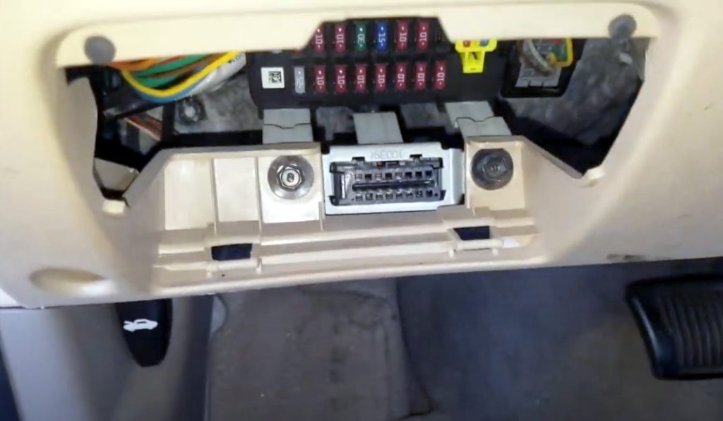
It is located under the panel on the driver’s side, behind the protective cover, there is also the diagnostic connector.

| 1 | 15A RR WIPER Glass tailgate wiper |
| 2 | 10A H / LP Left headlight bulbs |
| 3 | 25A FR WIPER Glass windshield wiper |
| 4 | 10A BLOWER Fan |
| 5 | 10A H / LP (RH) Right headlight bulbs |
| 6 | 20A S / ROOF Sunroof |
| 7 | 15A STOP LP Stop signals |
| 8 | 20A C / DR LOCK Central door lock switch |
| 9 | 15A IGN COIL Ignition Coil |
| 10 | 10A ABS Anti Lock Brake System |
| 11 | 10A B / UPLP Reversing light |
| 12 | BMS – Reserve |
| 13 | 25A C / LIGHTER Cigarette lighter |
| 14 | 10A FOLD’G Drive for folding outside rear-view mirrors |
| 15 | 20A HTR SEAT Heated Seat |
| 16 | 25A AMP Amplifier |
| 17 | 10A FR FOG LP Fog lights |
| 18 | 10A DRL Daytime Running Lights |
| 19 | 10A ECU Engine management system |
| 20 | 10A CLUSTER Instrument panel |
| 21 | 25A P / WDW RH Locking electric glass lifters (right side) |
| 22 | 10A AUDIO Audio system, trip computer |
| 23 | 10A RR FOG LP Rear fog lamp |
| 24 | 10A IGN Switch (ignition switch) |
| 25 | 30A HTD GLASS Heated rear window |
| 26 | 15A A / BAG Airbag |
| 27 | 10A TCU Automatic transmission control unit |
| 28 | 10A SNSR Sensors |
| 29 | SPARE – Reserve |
| 30 | 10А MULT B / UP Air conditioning control unit, clock, interior lighting ETACS |
| 31 | 15A AUDIO Audio system |
| 32 | 25A P / WDW LH Locking power windows (left side) |
| 33 | 10A HTD MIRR Heated exterior mirrors |
| 34 | 10A TAIL LP (LH) Left rear side light |
| 35 | 10A TAIL LP (RH) Right tail light |
| 36 | 10A HAZARD Alarm |
| 37 | 10A T / SIG LP Turn Signal Lights |
| 38 | 10A A / BAG IND Airbag warning lamp |
| 39 | 10A START Red Starter relay |
The cigarette lighter fuse is indicated on the diagram at number 13 at 25A.
On the back of the unit there are some relay elements: alarm and direction indicators, horn relay, etc.
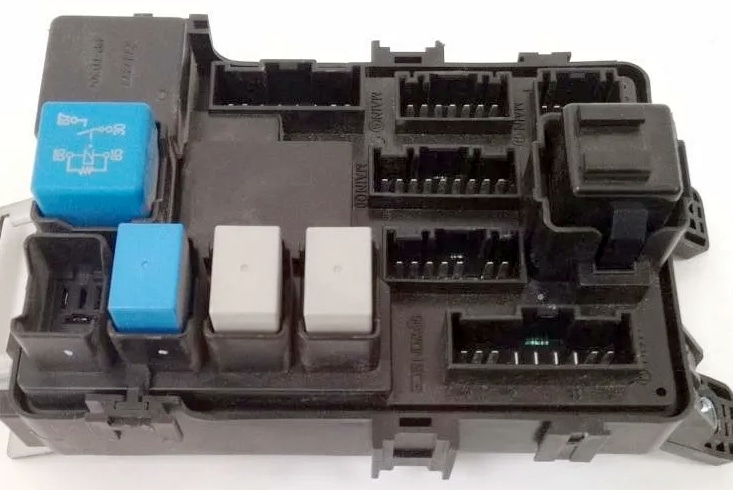
In sedans, a separate brake light relay is located at the rear, next to the rear signal control unit
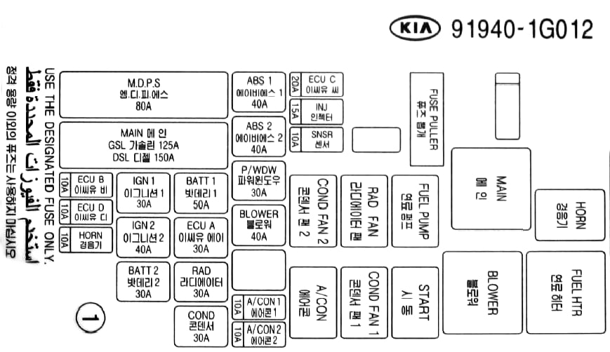
Engine compartment
Main fuse box
Located on the left side of the engine compartment.

An example of a diagram on the back of a protective cover

Designation
| 1 | 80A MDPS Electric power steering |
| 2 | 125 / 150A MIN Generator |
| 3 | 10A ECUB Engine Control Unit |
| 4 | 10A ECUD Engine Control Unit |
| 5 | 10A HORN Buzzer |
| 6 | 30A IGN1 Ignition switch (lock) |
| 7 | 40A IGN2 Starter, ignition switch (lock) |
| 8 | 30A BATT2 Generator, battery |
| 9 | 50A BATT1 Generator, battery |
| 10 | 30A ECUA Engine control unit |
| 11 | 30A RAD Electro radiator fan |
| 12 | 30A COND Electro condenser fan |
| 13 | 40A ABS1 ESP and ABS anti-lock brakes |
| 14 | 40A ABS2 ESP and ABS anti-lock brakes |
| 15 | 30A P / WDW Electro glass lifters |
| 16 | 40A BLOWER Relay for electric radiator fan |
| 17 | 10A A / CON 1 Air conditioner |
| 18 | 10A A / CON 2 Air conditioner |
| 19 | 20A ECUC Engine Control Unit |
| 20 | 15A INJ Fuel Injectors, air conditioning system |
| 21 | 10A SNSR Sensors |
| R1 | COND FAN 2 Relay for electric condenser fan (low speed) |
| R2 | RADFAN Radiator fan relay |
| R3 | FUEL PUMP Fuel pump relay |
| R4 | MAIN Main relay |
| R5 | HORN Horn relay |
| R6 | FUEL HTR Fuel filter heater relay |
| R7 | BLOWER Heater fan motor relay |
| R8 | START Starter relay |
| R9 | COND FAN 1 Relay for electric condenser fan (high speed) |
| R10 | A / CON Relay for air conditioner |
Additional box
Installed in models with diesel engines.
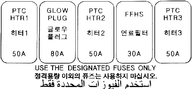
| PTC HTR 1 | 50A Heater RTS |
| GLOW PLUG | 80A Glow plug |
| PTC HTR 2 | 50A Heater RTS |
| FFHS | 30A Fuel filter heating |
| PTC HTR 3 | 50A Heater RTS |
If you have anything to add or if you have any questions, write everything in the comments.
Related posts:
Kia Ceed ED 1G – Fuse and Relay
The 1st generation Kia Ceed ED was produced in 2006, 2007, 2008, 2009, 2010, 2011 and 2012 with hatchback and station wagon bodies (ceed sw). During this time, the car has been restyled. In this publication, we will show the locations of the electronic control units, a detailed designation of the fuses and relays of the Kia Ceed ED 1st generation with boxes diagrams and photos – examples of execution. Note the fuse responsible for the cigarette lighter.

The location of the elements and boxes may differ from that shown and depends on the year of manufacture and the level of equipment of the Kia Ceed . And if the diagrames do not fit, check out the designation for the 2nd generation kia ceed.
Locations
General layout of all electronic units and control components.

| 1 | ABS electronic control unit |
| 2 | Air conditioning electronic control unit – in the air conditioning / heater control panel |
| 3 | Sunlight sensor (air conditioning) (with automatic light control) |
| 4 | A / C / Heater Blower Motor Control Module – Next to Blower Motor |
| 5 | Air conditioner / heater blower motor relay |
| 6 | Air purity sensor |
| 7 | Impact sensor, left |
| 8 | Shock sensor, right |
| 9 | Side impact sensor, left – top of the B-pillar |
| 10 | Side impact sensor, right – top of the B-pillar |
| 11 | Anti-theft alarm sound |
| 12 | Generator excitation resistor |
| 13 | Accumulator battery |
| 14 | Cruise control control unit (cruise control) |
| 15 | Diagnostic connector (DLC) |
| 16 | Power window relay – in the under-dash fuse / relay box |
| 17 | Electronic engine control unit |
| 18 | Fuse / relay box, engine compartment 1 |
| 19 | Fuse / relay box, engine compartment 2 (Diesel) |
| 20 | Fuse / relay box, instrument panel |
| 21 | Heated rear window relay – in the under-dash fuse / relay box |
| 22 | Beep (upper) |
| 23 | Beep (bottom) |
| 24 | Electronic immobilizer control unit (Diesel) |
| 25 | Immobilizer ring antenna – near the ignition switch |
| 26 | Instrument Cluster Illumination Rheostat Relay (with Daytime Lighting System) – In the under-dash fuse / relay box |
| 27 | Instrument cluster control unit |
| 28 | Multi-function switch control unit |
| 29 | Multifunctional control unit – functions: Anti-theft system, central locking, daytime running lights, power windows, hazard warning lights, headlights, heated rear window, heated windshield, interior lighting, seat belt monitoring, rear light relay, windshield wiper / washer |
| 30 | Ambient temperature sensor – 1 |
| 31 | Ambient temperature sensor – 2 |
| 32 | Parking Assist Control Unit – Behind Right Rear Trim Panel |
| 33 | Parking system buzzer |
| 34 | Power steering control unit |
| 35 | Rain sensor |
| 36 | Rear Window Wiper Relay – Behind Left Rear Trim Panel |
| 37 | Relay Box – Functions: Anti-theft alarm horn, central locking, heated windscreen, fog lights, rain sensor |
| 38 | Fixed power supply (stop-start system) |
| 39 | Seat heating control unit, left – under the seat |
| 40 | Seat heating control unit, right – under the seat |
| 41 | Brake light failure control unit – behind the right rear trim panel |
| 42 | Sunroof electric control unit |
| 43 | SRS electronic control unit |
| 44 | Tailgate relay – in the under-dash fuse / relay box |
| 45 | Tailgate Actuator Relay – In the under-dash fuse / relay box |
| 46 | Electronic gearbox control unit |
| 47 | Selector and / or ignition key lock control unit |
| 48 | Tire pressure monitor control unit |
| 49 | Displacement / acceleration sensor |
Passenger compartment
Fuse box
Located in the left end of the dashboard behind the protective cover.


For Example

Designation
| 1 | 10A Starter relay – START |
| 2 | 10A Air conditioner control unit – A / CON SW |
| 3 | 10A Heated exterior mirrors – HTD MIRR |
| 4 | 15A Seat heating – SEAT HTR |
| 5 | 10A Air Conditioning – A / CON |
| 6 | 10A High beam lamps – HEAD LAMP |
| 7 | 25A Windshield wiper – FR WIPER |
| 8 | 15A Tailgate wiper – RR WIPER |
| 9 | 15A Turning on the dipped headlights in the daytime – DRL OFF |
| 10 | 10A Rear fog lamps – RR FOG |
| 11 | 25A Glass lifter control unit – P / WDW LH |
| 12 | 10A Clock – CLOCK |
| 13 | 15A Cigarette lighter – C / LIGHTER |
| 14 | 20A Hatch, ignition control unit relay – DR LOCK |
| 15 | 15A Windshield heater relay – DEICER |
| 16 | 15A Stop lights – STOP |
| 17 | 15A Interior lighting – ROOM LP |
| 18 | 15A Audio system, trip computer – AUDIO |
| 19 | 15A Rear 5th door – T / LID |
| 20 | 25A Blocking power windows (right side) – SAFETY P / WDW RH |
| 21 | 25A Blocking power windows (left side) – SAFETY P / WDW LH |
| 22 | 25A Power Windows – P / WDW |
| 23 | 15A Power socket – P / OUTLET |
| 24 | 10A Switch Block – T / SIG |
| 25 | 10A Airbag Warning Lamp – A / BAG IND |
| 26 | 10A Instrument panel – CLUSTER |
| 27 | 15A Airbag – A / BAG |
| 28 | 15A Door or ignition control unit – IGN1-A |
| 29 | 15A Front Power Outlet – RR P / OUTLET |
| 30 | 10A Rear right marker lamp – TAIL RH |
| 31 | 10A Rear left marker lamp – TAIL RH |
The fuse number 13, 15A, is responsible for the cigarette lighter.
Relay boxes
Under the panel there can be 2 additional boxes with relays.

Location of relays
- rear light relay, power window relay, heater relay, tailgate relay
- central locking relay, windscreen defroster relay, rear fog lamp relay, anti-theft alarm horn relay, rain sensor relay, Built-in-ICM relay box
Engine compartment
Main box
The main box with fuses and relays is located on the left side next to the battery and is covered with a protective cover.
Option 1


Protected components
| 1 | 20A ABS and ESP – ABS2 |
| 2 | 40А ABS и ESP |
| 3 | 50A Electronic control unit for electrical equipment of the passenger compartment – B + 1 |
| 4 | 40A Heated mirrors – RR HTD |
| 5 | 40A Electro fan – BLOWER |
| 6 | 40A Electro Air Conditioning Fan – C / FAN |
| 7 | 20A Headlight washer – H / LP WASHER |
| 8 | 20А Reserve – SPARE |
| 9 | 125A Generator – ALTERNATOR |
| 10 | 80A Electric power steering – MDPS |
| 11 | 15A Front fog lamps – FR FOG |
| 12 | 10A Air Conditioning – A / CON |
| 13 | 15A Emergency signaling – HAZARD |
| 14 | 10А Reserve – SPARE |
| 15 | 20А Reserve – SPARE |
| 16 | 15A Fuel pump – F / PUMP |
| 17 | 15А Reserve – SPARE |
| 18 | 10A Engine control unit – ECU1 |
| 19 | 10A Engine control unit – ECU2 |
| 20 | 20A Engine control unit – ECU3 |
| 21 | 15A Fuel injectors, air conditioning – INJ |
| 22 | 10A Sensors – SNSR2 |
| 23 | 15A Sound signal – HORN |
| 24 | 50A Electronic control unit for electrical equipment of the passenger compartment – B + 2 |
| 25 | 40A Starter, ignition switch (lock) – ING2 |
| 26 | 30A Ignition switch (lock) – IGN1 |
| 27 | 30A Main relay – ECU |
| 28 | 10A Stability control system ESP, anti-lock braking system ABS, exchange rate sensor – ABS |
| 29 | 10A Ignition system – ECU2 |
| 30 | 10A Reversing Light Switch – B / UP |
| 31 | 10A Right headlight dipped beam – H / LP LO RH |
| 32 | 10A Left headlight low beam – H / LP LO LH |
| 33 | 20A High beam headlights – H / LP HI |
| 34 | 10A Sensors – SNSR1 |
| R1 | Cooling fan relay (low speed) – C / FAN2 |
| R2 | Cooling fan relay (high speed) – C / FAN1 |
| R3 | Starter relay – START |
| R4 | Fuel Pump Relay – F / PUMP |
| R5 | Air conditioner relay – A / CON |
| R6 | Headlamp Low Beam Relay – H / LP LO |
| R7 | Horn relay – HORN |
| R8 | Headlamp High Beam Relay – H / LP HI |
| R9 | Rear fog lamp relay – FOG LP |
| R10 | Wiper relay – WIPER |
| R11 | Main relay – MAIN |
Option 2


- Main relay
- Air conditioning
- Fuel pump
- The engine control unit
- ABS и ESP
- Reversing lamp switch
- Reserve
- Reserve
- Main relay
- Reserve
- Sensors
- The engine control unit
- Sensors
- Reserve
- Fuel injectors, air conditioning system.
- Air conditioning
- The engine control unit
- Fuel pump
- Electro fan
- High beam relay
- Sound signal
- High fan speed
- Starter relay
- Rear foglights
- Glass cleaner
- Low fan speed
- Low beam left
- Low beam right
- Reserve
- Low beam relay
- ABS ESP
- ABS ESP
- Front fog lights
- Reserve
- Electronics unit salon
- Reserve
- Buzzer and its relay
- Electric power steering
- Starter and ignition switch
- Heated mirrors
- Fan (air conditioner)
- Electro fan
- Generator
- Egnition lock
- Electric cabin control unit
- Reserve
Check the assignment against your diagram on the back of the protective cover.

Additional box

Used in diesel engines only.

Designation
- 12 – fuel filter heater relay
- 13 – relay # 3 PTC heater
- 14 – relay # 2 PTC heater
- 15 – relay # 1 PTC heater
- 16 – glow plug relay
If you want to help complete the material, write everything in the comments.